
Getting Started
Attaching the Air Hose and Air Filter
Attaching & Cleaning an Air Filter
Adjusting the Check Valve/Unloader
Air Lock
When pressure is left in an air tank for prolong periods of time, the check valve spring can become compressed cause the motor to not start.
Resolve Issue:
1. Turn off and unplug the air compressor,
2. Drain the air tank from the drain valve.
3. Locate the check valve on the parts diagram in manual
4. Remove the hex nut cap on the check valve. (see picture below)
5. Remove the spring located inside the check valve.
6. Clean the inside of the check valve.
7. Clean and enlong the spring
8. Replace the spring and cap.
9. Close the drain valve
10. Plug in the power cord and turn on the air compressor.
CHECK VALVE TUTORIAL

80060C Check Valve Adjustment
Adjusting the Kick On & Kick Off PSI
Air Compressors are on-demand tools.
An air compressor will start (Kick On) when the pressure (PSI) in the air tank drops to a pre-set PSI (example 90 PSI).
The air compressor will continue to run until the pressure (PSI) in the air tank reaches the Max PSI (that is pre-set) and Kick Off (shut off) (example Max 120 PSI for 1.0 Hp, Max 125 PSI for most 2.0, 4.0 and 6.0 Hp models).
The maximum PSI cannot exceed the maximum 140 PSI safety valve.
If the PSI exceeds the maximum PSI of the safety valve, the safety valve will open and release air as a saftey precaution.
The Kick On and Kick Off PSI is set for a 30 PSI spread (example 90 PSI to 120 PSI). You may increase tank pressure in 10 PSI increments (i.e. from 90 PSI Kick On to 100 PSI Kick On, but the 30 PSI spread cannot be changed).**
Refer to video below to adjust the Kick On and Kick Off PSI. There is a set screw you turn to move the Kick On and Kick Off PSI.
NOTE: The pressure range and output pressures are adjustable; for the majority of California Air Tools air compressors the default regulated output pressure is 90 PSI (assumes the pressure regulator control knob is turned fully CW).


This is a micro adjustment to the pressure switch set screw…only turn it clockwise or counterclockwise 1/4 of a turn at a time. For example, you may set higher or lower to the ranges listed below. You will need to test and confirm the final range several times by releasing air from the tank.
For example, with 2.0, 4.0 and 6.0 Hp compressors, you can set pressure switch KICK ON/KICK OFF to the following approximate ranges (+/- 5%):
111-140 (not suggested for 1.0 or 2.0 Hp models)
102-133 (i.e. required for some laser/CNC/milling machines)
92-123 (2.0, 4.0 & 6.0 Hp Default PSI tank pressure range)
82-113
72-103
62-93
Then you may connect to your tooling/application.

NOTE: Do not exceed the upper limit of 140 PSI as the pressure (safety) relief valve will open and release air from the tank.
For example, the CAT-20040DCAD pressure switch can be adjusted to 100-130 PSI tank pressure range; output regulated pressure can then be maintained at ~100 PSI:
**CAT-60065C / CAT-80060C air compressor models regulated output pressure may NOT BE adjusted any higher than the 90 PSI default air output pressure.
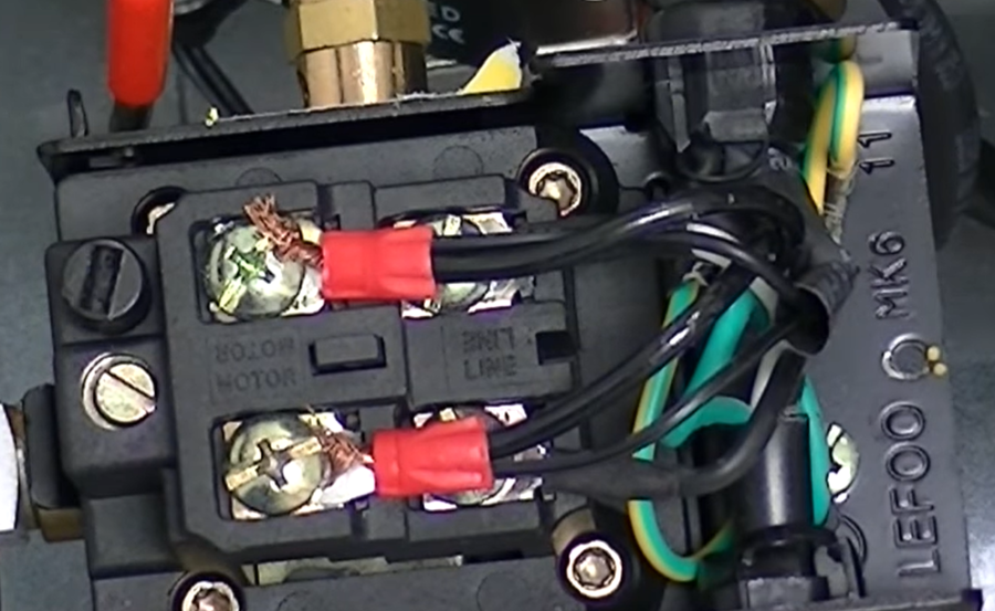
Wiring Pressure Switch

Test Pressure Switch

Automatic Drain Valve
Demonstrations
Optional PTFE Black Hose Tubing, 8 mm (10 feet) to connect to Automatic Drain Valve, Air Dryer Valve or Condensate port
Service

Air Leaks
Leaking Air at Fitting or Connections
Tank fails to build any or very little air pressure as observed on main Tank Pressure Gauge.
Diagnose & Resolve Issue:
1. Turn on air compressor and build pressure in the tank.
2. Brush soapy water on air connections and look carefully for air bubbles.
(refer to compressor components below for reference, i.e. 1 Hp units)
3. Tighten leaky connections.

Manual Ball Drain Valve Open
Resolve Issue:
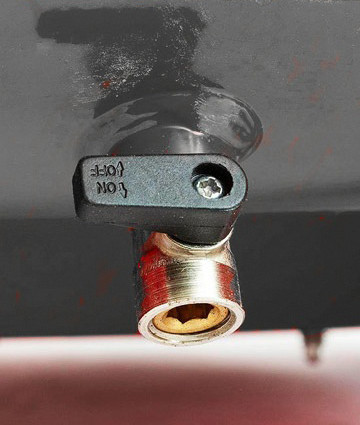
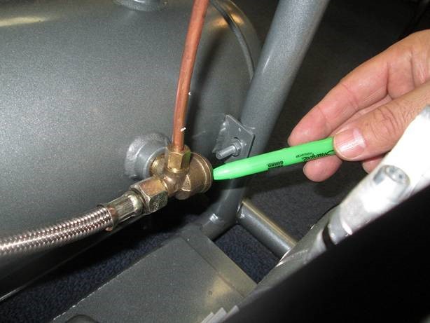
1. At the bottom of all Standard air compressor tanks is a Manual Ball Drain Valve. Refer to photo below – ball valve is shown in OPEN position.
2. Close the Manual Ball Drain Valve to eliminate air leaking.

Air Leaking from Check Valve
Check Valve Spring inside Check Valve could be compressed (stuck) or have residual particulates built up on spring/plunger. NOTE: If air pressure is left in an air tank for prolong periods of time, the check valve spring can become compressed.
Resolve Issue:
1. Turn off and unplug the air compressor,
2. Ensure tank has no pressure inside as indicated on Main Tank gauge. Drain the air tank from the manual drain valve or via an Air Hose connected to output air port.
3. Locate the check valve on the parts diagram in manual (this is a brass fitting affixed to top of main tank with several air lines connected to it). See photo below.
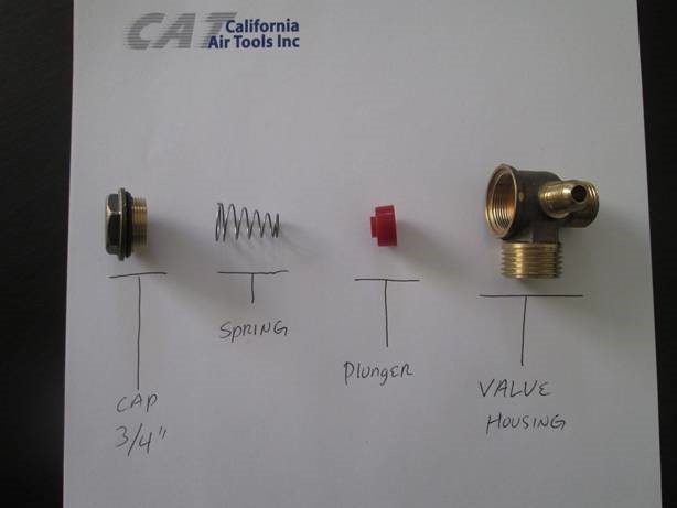
4. Remove the 3/4″ hex nut cap on the check valve. See video below for reference.
5. Remove the spring and plunger located inside the check valve.
6. Clean the inside of the check valve and thoroughly clean the spring and plunger with warm soapy water.
7. Clean and elongate the spring. TIP: It is suggested to spray a little WD-40 onto spring.
8. Replace the spring, plunger and Hex Nut cap.
9. Close the manual ball drain valve.
10. Retest compressor for proper operation.


Manifold Regulator Leaking Air
Manifold Regulator Leaking Air – Models: 20020, 20020AD, 10020C, 10020CAD, etc.
Resolutions Steps:
1. Turn off and unplug the air compressor.
2. Drain the air tank from the drain valve.
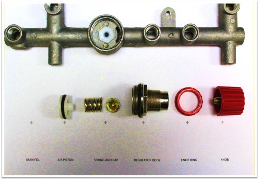
3. Clean the regulator
4. Remove the regulator body from the manifold with a wrench.
5. Clean the regulator body, air piston, spring and cap with WD40.
6. After cleaning replace the parts.

CAUTION: Replacing the Industrial Female fitting on a new unit will void your warranty if damage occurs. The Female fitting (or fittings) is attached with high-grade RED locktite to the manifold and can only be removed using a Heat Gun. The manifold assembly may crack and leak air if improperly modified. For servicing personnel only!

Automatic Drain Valve Clogged
If the Automatic Drain Valve is leaking air, it could be due to metal debris inside the solenoid of the auto drain, which can clog the device and keep it open, allowing air to escape. To resolve this issue, it is suggested to open up the Auto Drain Valve and thoroughly clean its components. Refer to Auto Drain Owners Manual.


Electronic Unloader Valve Failure
If you suspect an Electronic Unloader Valve Failure with a California Air Tools 2 Hp, 4 Hp or 6 Hp air compressor, perform the following resolution steps:
Symptoms:
-Electronic Unloader Valve LED (red or green) is not illuminated when motor/pump(s) are running
-Air is continually leaking (blowing) out of Electronic Unloader Valve (see videos below).
Resolutions:
1. Clean or Replace Check Valve
2. Replace Electronic Unloader Valve
80% Dry Air Model – Leaking Air From Drain Valve
For California Air Tools 80% Dry Air Compressor that fails to build pressure and air is observed being purged out of 80% air dryer drain tube, then perform the following resolution steps:
Symptoms of a clogged 80% air drying system:
-Desiccant Drain purges air nonstop (air blows out of drain tube continuously).
-Tank fails to build pressure (i.e. Tank Gauge reads zero or very low).
– If Air Drain Tube is blocked, tank is allowed to build up pressure.
Resolution Steps:
1. Remove and Replace Desiccant pouch (1 lb bag). …Part Number: DY Desiccant (1 lb):
Purchase Desiccant – Click Here
2. Remove Bottom Cap. Thoroughly clean center (inner) Auto Drain Valve part of all residues – use warm soap and water. Part Number: PW-1039
Compressor Pressure Dropping
Drop in Pressure
Air Leaking at Connection
Resolve Issue:
1. Turn on air compressor and build pressure in the tank.
2. Brush soapy water on air connections and look carefully for air bubbles. 3. Tighten leaky connections.
Drain Valve Open
Resolve Issue:
1. At the bottom of all air compressor tanks is a drain valve.
2. Close the drain valve to eliminate air leaking.
Air Leaking (releasing) from Valve
Check Valve Spring is Compressed (sticking) or Dirty
When pressure is left in an air tank for prolong periods of time, the check valve spring can become compressed. The spring may also be contaminated/dirty with oxidized residue which can cause it to stick.
Resolution Steps:
1. Turn off and unplug the air compressor,
2. Drain the air tank from the drain valve.
3. Locate the check valve on the parts diagram in manual
4. Remove the hex nut cap on the check valve. (see picture below)
5. Remove the spring located inside the check valve,
6. Clean the inside of the check valve.
7. Clean and enlong the spring
8. Replace the spring and cap.
9. Close the drain valve
10. Plug in the power cord and turn on the air compressor.
Not Building Pressure
Possible causes of failure symptoms:
- Check Valve Dirty or Unloader Valve may have failed – see video below.
- Motor/Pump Piston Ring or Reed Valves are Worn.
- Over time piston rings and reed valves can wear because of usage.
- Standard maintenance is required – typically after 2000-6000 operating/running hours depending on specific motor/pump model.
- If air is pushing out from the air filter and not sucking into the air filter, then the Reed Valve or Valves are bent or damaged.
Resolutions:
- Replace the piston rings and reed valves.
- Replace Motor/Pump
Not Building Pressure
Tank fails to build any or very little air pressure as observed on main Tank Pressure Gauge.
Possible causes of failure symptoms:
- Check Valve Dirty or Unloader Valve may have failed – see video below.
- Motor/Pump Piston Ring or Reed Valves are Worn.
- Over time piston rings and reed valves can wear because of usage.
- Standard maintenance is required – typically after 2000-6000 operating/running hours depending on specific motor/pump model.
- If air is pushing out from the air filter and not sucking into the air filter, then the Reed Valve or Valves are bent or damaged.
Resolutions:
- Replace the piston rings and reed valves.
- Replace Motor/Pump
80% Dry Air Model – Leaking Air From Drain Valve
For California Air Tools 80% Dry Air Compressor that fails to build pressure and air is observed being purged out of 80% air dryer drain tube, then perform the following resolution steps:
Symptoms of a clogged 80% air drying system:
-Desiccant Drain purges air nonstop (air blows out of drain tube continuously).
-Tank fails to build pressure (i.e. Tank Gauge reads zero or very low).
– If Air Drain Tube is blocked, tank is allowed to build up pressure.
Resolution Steps:
1. Remove and Replace Desiccant pouch (1 lb bag). …Part Number: DY Desiccant (1 lb):
Purchase Desiccant – Click Here
2. Remove Bottom Cap. Thoroughly clean center (inner) Auto Drain Valve part of all residues – use warm soap and water. Part Number: PW-1039
No Air Output (Tank Pressure is Ok)
Manifold Regulator Internally Damaged
Models: 4610, 4620, 5020W, 10020C, 10020CAD, 20020, 20020AD, etc.
Symptoms:
1. Tank Pressure Gauge reads normal and correct (i.e. 120 PSI) which signifies the motor-pump, pressure switch, check valve and unloader valve are functioning correctly.
2. Regulator Pressure Gauge reads zero (0 PSI), or excessively low (i.e. less than 20 PSI), and no air output is available for tooling.

Resolve Issue:
1. Turn off and unplug the air compressor.
2. Drain the air tank from the drain valve.
3. Replace the regulator assembly
NOTE: in some cases cleaning the regulator may correct the issue if pressure is partially available (i.e. 20 PSI range or similar).
4. Remove the regulator body from the manifold with a wrench.
5. Replace the regulator body, air piston, spring, cap and knob.
CAUTION: Replacing the original Industrial Female fitting on a new unit will void your warranty if damage is incurred. The Industrial female fitting (or fittings) is attached with high-grade locktite to the manifold and should only be removed using a heat gun in order to loosen the locktite. The manifold assembly may crack and leak air if improperly modified. For servicing personnel only!

Desiccant Maintenance
Version en Español
DCADC/DCC Filter System Maintenance
Filter System Maintenance (DCADC Series)
The Filter System Maintenance procedure applies to all California Air Tools DCADC dry air models that feature the Ultra Dry Cartridge Spin-On Filter:
10020HDCADC
10020HDCADC-22060
10020HDSMADC
10020HDSPCADC
20040DCADC
20040DSPCADC
20040DSMADC
60040DCADC
60040DSMADC
20060DCC
Maintenance includes replacement of the Dry Air Unit Spring and Unloader Valve Assembly (i.e. Inner Piston).
To perform filter system maintenance and replace the Dry Air Unit Spring and Unloader Valve Assembly (also referred to as the INNER PISTON), perform the following steps:
1. Using a #22 open-ended wrench, remove the muffler tube clamp, tube and muffler filter. The unit may need to be lifted up slightly and supported in order to remove the 3 parts.
2. Using a #11 metric open-ended wrench, remove the 2 bolts securing the main piston disc, along with the elbow & small tubing located on the check valve. Set the parts aside.
3. Next, remove the Dry Air Unit Spring and Unloader Valve Assembly, commonly referred to as the Inner Piston assembly. You may need to gently pry the inner piston out with a small flathead screwdriver.
NOTE: there is an o-ring attached to the internal dryer assembly and may fall out when the main disc or inner piston are removed; ensure the o-ring is present and reinstalled prior to main disc reinstallation.
4. To confirm proper function of inner piston assembly, push inner bolt inside center of the inner piston — this should force out the half ball seal located in front. If necessary, clean and lubricate the inner piston prior to reinstallation.
5. Prior to reinstallation of the main piston ensure the inside o-ring is set correctly.
6. With the inner piston’s hole facing down, slide the inner piston fully into the seated position. The inner piston should gently lock into the groove below.
7. Reinstall the main piston disc by orientating into the position as shown and twist into place. Reconnect elbow, tubing and secure main disc with 2 bolts.
8. Thoroughly clean the filter with warm water. Once cleaned, reinstall filter, tube and tube clamp.
9. This completes the filter system maintenance procedure.
Ultra Dry Service Kit (Filter) Replacement
This Ultra Dry Service Kit (Filter) Replacement procedure applies to all California Air Tool DCADC dry air models that feature the Ultra Dry Cartridge Spin-On Filter (molecular sieve desiccant).
Perform the following steps:
- Obtain Ultra Dry Cartridge Strap Wrench.
- Position Strap wrench belt around the Ultra Dry Spin-On filter and turn Counter-Clockwise.
- Remove and replace the Ultra Dry Filter.
- Turn fully Clockwise; attach the Ultra Dry Cartridge Strap Wrench and tighten.
Ultra Dry Cartridge Service Kit (Part Number 619003):
Ultra Dry Cartridge Strap Wrench (Part Number 619003-S):
Installing Automatic Drain Valve
Installing the Automatic Drain Valve on a 10020CAD
1. Unpackage the Air Compressor
2. Remove the Auto Drain Valve that is attached to the compressor frame.
3. Lay air compressor on it’s side. (carefully)
4. Attach the Auto Drain Valve to the female quick connector located at
the bottom of the air compressor air tank.
The fitting are Push-In to connect air fittings.
5. Stand up the air compressor and read the Owner’s Manual to get started.
Motor/Pump Features & Wear Parts
Air Compressor Wear Parts and Losing Pressure
Partes de compresor
Motor Reassembly
NOTE: A motor-pump is NOT an air compressor. A replacement motor-pump can be easily installed (spliced) into existing California Air Tools equipment.
CAUTION: If installing onto a Non-California Air Tools air compressor or unique application you will need to have the electrical and mechanical knowledge for properly installing a California Air Tools motor-pump. It is important to properly configure an UNLOADER valve and CHECK VALVE with the motor pump (to correctly bleed pressure off of the pistons) otherwise damage to motor may occur.
Motor/Pump Piston Seal Replacement (60065C & 80060C Air Compressors)

To replace the piston seals on the CAT-60065C (4 seals total) and CAT-80060C (8 seals total) air compressors, obtain Piston Seal 4-Pack Kit P/N: 91457-4p
Perform the following steps:
1. Turn off power and unplug the air compressor.
2. Drain the air tank by opening the manual ball drain valve.
3. Remove the 16 motor-head securing bolts (8 bolts from each side of Quad Motor/Pump). Remove and set aside the two (2) motor head assemblies onto support chassis.
Note: braided air hoses may remain connected.


4. Gently grasp and remove the piston/housing from each piston rod by pulling straight out. All four (4) piston plates and seals should be visible – see photos below.


5. Using a Heat Gun ONLY, heat up piston rod bolt for 3-5 minutes. Using an allen-head wrench turn bolt counterclockwise to remove.
Note: bolt must be very hot in order to loosen/turn.
Caution: use gloves when removing piston rod bolt.

6. Disassemble and remove worn piston seal from piston plate; replace with new piston seal.
7. Reinstall piston rod bolt and turn clockwise. Firmly tighten to secure piston plate.
8. Repeat steps 6 & 7 for remaining piston plates/seals.
Note: Quad motor/piston pump may need to be removed from air compressor, via 4 securing bolts at base, and placed onto a work bench for easier piston/housing reassembly.

9. Perform steps 1-4 in reverse order.
10. Close manual ball drain valve.

11. Plug in the power cord and turn on the air compressor.
12. Verify 60065C/80060C air compressor is operating normally.
Confirm time to fill 80060C tank from empty to full takes approximately 3 min 56 secs.
Confirm time to fill 60065C tank from empty to full takes approximately 3 min 18 secs.
Not Starting
Air Compressor Not Starting
Lack or Insufficient Power
1. Check that the main voltage (power supply or outlet) corresponds to the air compressor specifications.
2. An extension cord that is too thin or too long can cause a voltage drop and cause the motor to overheat. An extension cord of 12 or 14 gauge and up to 25 feet long may be satisfactory for use.
3. GFCI (general fault circuit interruptors) incorporated into most new households today may interfere with compressor start – switch to a different electrical outlet to test.
4. Generator, Inverter or Solor Battery power source is too small and produces too few watts to run the air compressor.
Motor-Pump Overheating / Motor Failure
The thermal protector (internal motor-pump fuse) temporarily opened because the motor is overheating. With the exception of the CR series air compressors do not run motor continuously (non-stop) for more than 1 hour.
Mutiple times of overheating will permenately burn and danage the motor windings. If this occurs then the motor-pump will need to be replaced.
NOTE: With the exception of the CR compressor series, the majority of California Air Tools air compressors have a 70/30 Duty Cycle Rating
Electrical Connectivity Issue
Vibration from compressor use/transport may have loosened a securing screw and might be interferring with electrical connectivity to pressure switch.
Remove power from air compressor by unplugging the power cable from power source. Remove the pressure switch cover (box) by removing 1 screw. Loosen and then retighten all screws which secure wired electrical connections. Reinstall cover and reapply power.
Air Lock (check valve spring compressed)
When pressure is left in an air tank for prolong periods of time, the check valve spring can become compressed cause the motor to not start.Resolve Issue:
1. Turn off and unplug the air compressor,
2. Drain the air tank from the drain valve.
3. Locate the check valve on the parts diagram in manual
4. Remove the hex nut cap on the check valve. (see picture below)
5. Remove the spring located inside the check valve.
6. Clean the inside of the check valve.
7. Clean and enlong the spring
8. Replace the spring and cap.
9. Close the drain valve
10. Plug in the power cord and turn on the air compressor.
2010A Check Valve Adjustment (generally applies to most models):
1P1060S/SP Check Valve Adjustment (generally applies to most models):
Tank is Full of Water
Pressure Switch Failure
Pressure switch worn or damage.
Motor not receiving power from the pressure switch.
Excess water in the air tank or compressor usage over time may cause the pressure switch to fail.
Resolve Issue: Replace Pressure Switch


Pressure switch not turning on.
Resolve Issue: Check contacts inside the pressure switch and tighten
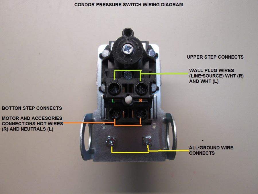
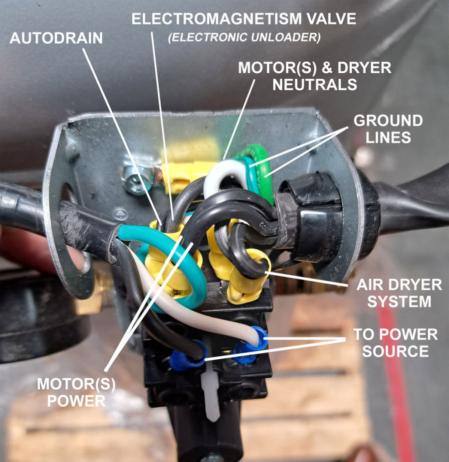
i.e. Reference 60040DCAD Pressure Switch Wiring shown below
Noisy
Motor / Pump Failure and Symptoms
Possible causes of failure
- Piston Ring or Reed Valves are Worn.
- Over time piston rings and reed valves can wear because of usage.
- Standard maintenance is required – typically after 2000-6000 operating/running hours depending on specific motor/pump model.
- If air is pushing out from the air filter and not sucking into the air filter, then the Reed Valve or Valves are bent or damaged.
Resolutions:
- Replace the piston rings and reed valves.
- Replace Motor/Pump
Replacing a Motor/Pump
Motor / Pump failure and symptoms:
Possible causes of failure symptoms:
- Piston Ring or Reed Valves are Worn.
- Over time piston rings and reed valves can wear because of usage.
- Standard maintenance is required – typically after 2000-6000 operating/running hours depending on specific motor/pump model.
- If air is pushing out from the air filter and not sucking into the air filter, the Reed Valve or valves are bent/damaged.
Resolutions:
- Replace the piston rings and reed valves.
- Replace Motor/Pump
NOTE: A motor-pump is NOT an air compressor. A replacement motor-pump can be easily installed (spliced) into existing California Air Tools equipment – refer to video above.
CAUTION: If installing onto a Non-California Air Tools air compressor or unique application you will need to have the electrical and mechanical knowledge for properly installing a California Air Tools motor-pump. It is important to properly configure an UNLOADER valve and CHECK VALVE with the motor pump (to correctly bleed pressure off of the pistons) otherwise damage to motor may occur.
i.e. Reference 60040DCAD Pressure Switch Wiring

SMART Air Compressor Firmware Update Instructions
SMART Air Compressor Firmware Update Instructions
The firmware of your Smart Controller can be updated, improving important aspects to make the device and its control more efficient.
Applies to the following California Air Tools compressor models:
- CAT-10020SMHAD
- CAT-10020DSMAD
- CAT-10020HDSMADC
- CAT-20040SM
- CAT-20040SMAD
- CAT-20040DSMADC
- CAT-60040SMAD
- CAT-60040DSMADC
A. Check your firmware version:
1. Use your device and enter the Smart Controller’s control interface
2. Go to the “Condition Monitoring” tab.
3. Note in the “Device Info” box the date and time shown in the “Build Time” section.

B. If your firmware is outdated, continue:
1. Download the firmware file to your computer or mobile device – refer to .zip file below.
2. Go to the control interface and go to the “OTA Update” tab
3. Select “Browse…” to browse to the .bin firmware file
4. Select the file and press “Update Firmware”

The Smart Controller will start uploading the file and when it finishes it will restart the computer. Wait 15 seconds before operating the air compressor.